Tuesday 29 September 2015

how to check OS and version using Console

# cat /etc/*release*
# cat /etc/redhat-release 
# cat /proc/version
# cat /etc/issue
# lsb_release -a  
# cat /etc/lsb-release 
# cat /etc/issue.net
# cat /etc/debian_version 

Resize EC2 instance EBS root device

Today I stumbled upon the problem that resizing the root EBS volume of a just launched EC2 instance (running CentOS 6) did not work.

I tried to run the following command:"resize2fs /dev/xvde1"
This returned with:The filesystem is already x blocks long. Nothing to do!

However I was pretty sure that there was still roughly 1TB extra available for me. I figured out how to resolve this, with the following commands:
1. Connect to the instance over ssh2. "fdisk /dev/xvde1"3. Press "p" + ENTER to view the current partitions, remember the ID of your partition4. Fill in "d 999", where 999 represents the partition ID from step 3, hit ENTER (this will delete your partition)5. Press "n" + ENTER to start creating a new partition6. Press "p" + ENTER to mark it as a primary partition7. Select the first cylinder by entering "1" and hitting ENTER8. Your start and end block can be default (e.g. 1 and 1234567)9. Press "a" to mark the partition as bootable10. Now we're done press "w" to write the partition table, this will cause you to get an error, don't worry11. Reboot your instance to reload the partition table (as mentioned in the error you received on step 10)12. Connect to your instance again over ssh13. Run "resize2fs /dev/xvde1", this might take a while, it performs an online grow of the partition14. Once the resize2fs command has finished you can validate the results by running "df -h"
Good luck with resizing your EC2 instance root devices!

Source : http://www.robinverlangen.nl/index/view/5035f20d64fa0-d74cc2/resize-ec2-instance-ebs-root-device.html

Versi lain
=========
1. Stop the instance
 2. Create a snapshot from the volume
 3. Create a new volume based on the snapshot increasing the size
 4. Check and remember the current's volume mount point (i.e. /dev/sda1)
 5. Detach current volume
 6. Attach the recently created volume to the instance, setting the exact mount point
 7. Restart the instance
 8. Access via SSH to the instance and run fdisk /dev/xvde
 9. Hit **p** to show current partitions
 10. Hit **d** to delete current partitions (if there are more than one, you have to delete one at a time) NOTE: Don't worry data is not lost
 11. Hit **n** to create a new partition
 12. Hit **p** to set it as primary
 13. Hit **1** to set the first cylinder
 14. Set the desired new space (if empty the whole space is reserved)
 15. Hit **a** to make it bootable
 16. Hit **1** and **w** to write changes
 17. Reboot instance
 18. Log via SSH and run resize2fs /dev/xvde1
 19. Finally check the new space running df -h
Source : http://stackoverflow.com/questions/11014584/ec2-cant-resize-volume-after-increasing-size

Add Another Local Disk on XenServer as a new Storage Repository

from xenserver console:

fdisk -l

that should return an error like this:

Disk /dev/sdb doesn't contain a valid partition table

your local hard drive is "/dev/sdb" or whatever the error the first command shows you

run this command

xe host-list

that will return something like this:
uuid ( RO) : 3614fba9-f5fc-1c57-0b42-58513c51fc1c
name-label ( RW): xenb
name-description ( RO): Default install of XenServer

copy the UUID of your host server to the clipboard.


xe sr-create host-uuid=<your host UUID> content-type=user type=lvmohba device-config:device=/dev/sdb shared=false name-label="Local_Stor_2"

if you get an error you may need to unmount your current local storage in order to add the new one.
to do this, run this command:

xe pbd-list

get the UUID of your current storage

run this:
xe pbd-unplug uuid=<your storage UUID>

then try mounting your Hardware HBA through Xencenter.
This worked for me, hope it does for you too

Source : http://www.serveroperations.net/citrix/add-another-local-disk-on-xenserver-as-a-new-storage-repository

Tuesday 15 September 2015

Mikrotik Cloud – a Dynamic DNS name and NTP service


When you setup a router in a site that does not have a static public IP address, you would usually have to rely on 3rd party Dynamic DNS services to provide you access to the device/site without knowing the current IP address.  This involved running scripts on the router to constantly update the DNS records.
Starting with RouterOS 6.14, Mikrotik have added a new feature called Cloud.¬†When enabled, it will generate a DNS name based on your router’s serial number. It also provides an NTP service. This will avoid having to run scripts to update the ip address if you use ntp servers like¬†ntp.pool.org and will not require any script to update the ip address at the 3rd party dynamic DNS name providers. Agreed, the generated DNS name is not a friendly one since it is based on the serial no but it should not be something you need to remember regularly since you can save the details in winbox.
To enable the Cloud service through command line:
/ip cloud set enabled=yes
To enable the NTP service (Update Time):
/ip cloud set update-time=yes
To view the settings and note the DNS Name:
/ip cloud print
The output will be similar to the below:
enabled: yes
update-time: yes
public-address: 0.0.0.0
dns-name: serialnumber.sn.mynetname.net
status: updated
Please note: Since v6.27 /ip cloud set enabled has changed to
/ip cloud set ddns-enabled
You can also enable it through Winbox or Webbox by clicking on the IP menu and click on Cloud.

Then tick the box marked Enabled and Update Time, if you require time sync. As soon as you click Apply, your DNS Name will be generated and it will show the current Public IP address

I personally like these new features and will definitely make use of them.
This seems to be a very popular post with daily hits. Don’t be shy! Let me know if you find it useful or if something needs to be changed! :)
UPDATE: I have written a blog post for using the Mikrotik Cloud IP DDNS when you have multiple ISPs. You can find it here.

Source = http://www.phy2vir.com/mikrotik-cloud-a-dynamic-dns-name-and-ntp-service/

Saturday 12 September 2015

How To Setup Your Own VPN With PPTP

Intro

One of the commonly asked questions from our users is how to add another IP address to their server. You can assign your own private IP address to your droplet by creating a VPN tunnel. Whether you want to build your own Virtual Private Network (VPN), or assign an SSL certificate to that IP address, you have several options. From all of the possible options, the most optimal ones are between PPTP and OpenVPN. A Point-To-Point Tunneling Protocol (PPTP) allows you to implement your own VPN very quickly, and is compatible with most mobile devices. Even though PPTP is less secure than OpenVPN, it is also faster and uses less CPU resources.

Step 1 - PPTP Installation

You will have to select one server to be responsible for handling out IPs to others and authenticating all of your servers into your VPN. This will become your PPTP Server.
On CentOS 6 x64:
rpm -i http://poptop.sourceforge.net/yum/stable/rhel6/pptp-release-current.noarch.rpm
yum -y install pptpd
On Ubuntu 12.10 x64:
apt-get install pptpd
Now you should edit /etc/pptpd.conf and add the following lines:
localip 10.0.0.1
remoteip 10.0.0.100-200
Where localip is IP address of your server and remoteip are IPs that will be assigned to clients that connect to it.
Next, you should setup authentication for PPTP by adding users and passwords. Simply add them to /etc/ppp/chap-secrets : 
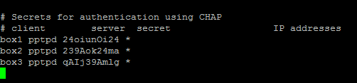
Where client is the username, server is type of service – pptpd for our example, secret is the password, and IP addresses specifies which IP address may authenticate. By setting ‘*’ in IP addresses field, you specify that you would accept username/password pair for any IP.

Step 2 - Add DNS servers to /etc/ppp/pptpd-options

ms-dns 8.8.8.8
ms-dns 8.8.4.4
Now you can start PPTP daemon:
service pptpd restart
Verify that it is running and accepting connections:

Step 3 - Setup Forwarding

It is important to enable IP forwarding on your PPTP server. This will allow you to forward packets between public IP and private IPs that you setup with PPTP. Simply edit /etc/sysctl.conf and add the following line if it doesn’t exist there already:
net.ipv4.ip_forward = 1
To make changes active, run sysctl -p

Step 4 - Create a NAT rule for iptables

iptables -t nat -A POSTROUTING -o eth0 -j MASQUERADE && iptables-save
If you would also like your PPTP clients to talk to each other, add the following iptables rules:
iptables --table nat --append POSTROUTING --out-interface ppp0 -j MASQUERADE
iptables -I INPUT -s 10.0.0.0/8 -i ppp0 -j ACCEPT
iptables --append FORWARD --in-interface eth0 -j ACCEPT
Now your PPTP server also acts as a router.
If you would like to restrict which servers can connect to your droplets, you can setup an iptables rule that restricts TCP connects to port 1723.

Step 5 - Setup Clients

On your client servers, install PPTP client:
yum -y install pptp

Step 6 - Add necessary Kernel module

modprobe ppp_mppe
Create a new file /etc/ppp/peers/pptpserver and add the following lines, replacing name and password with your own values:
pty "pptp 198.211.104.17 --nolaunchpppd"
name box1
password 24oiunOi24
remotename PPTP
require-mppe-128
Where 198.211.104.17 is the public IP address of our PPTP server, with username ‘box1’ and password ‘24oiunOi24’ that we specified /etc/ppp/chap-secrets file on our PPTP server.
Now we can ‘call’ this PPTP server, since this is a point-to-point protocol. Whichever name you gave your peers file in/etc/ppp/peers/ should be used in this next line. Since we called our file pptpserver:
pppd call pptpserver
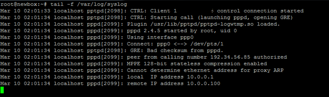
You should see successful connection from PPTP server logs:
On your PPTP client, setup routing to your private network via ppp0 interface:
ip route add 10.0.0.0/8 dev ppp0
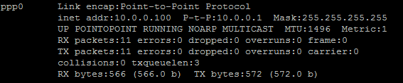
Your interface ppp0 should come up on PPTP client server, and can be checked by running ifconfig
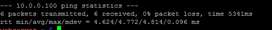
Now you can ping your PPTP server and any other clients that are connected to this network:
We can add our second PPTP client to this network:
yum -y install pptp
modprobe ppp_mppe
Add to /etc/ppp/peers/pptpserver (replacing with your own name and password values):
pty "pptp 198.211.104.17 --nolaunchpppd"
name box2
password 239Aok24ma
remotename PPTP
require-mppe-128
Now run on your second client the following:
pppd call pptpserver
ip route add 10.0.0.0/8 dev ppp0
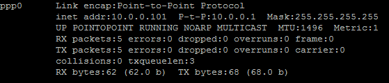
You can also ping the first client, as packets would go through the PPTP server and be routed using the iptables rules we’ve placed earlier:
This setup allows you to create your own virtual private network:
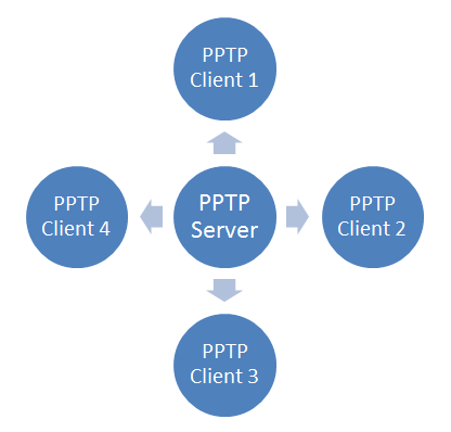
If you wanted to have all of your devices communicating securely on one network, this is a quick way of implementing it.
You can use it with Nginx, Squid, MySQL, and any other application you can think of.
Since traffic is 128-bit encrypted, it is less CPU-intensive than OpenVPN, and still provides an added level of security to your traffic.

Source = https://www.digitalocean.com/community/tutorials/how-to-setup-your-own-vpn-with-pptp

Wednesday 9 September 2015

Pengertian dan Konsep RAID

RAID merupakan kependekan dari “Redundant Array of Independent Disk”. Konsep RAID diciptakan untuk mendapatkan kapasitas yang lebih besar dan/atau Fault tolerance yang disebabkan oleh kerusakan Harddisk. Fault Tolerance adalah kemampuan dari suatu system untuk dapat tetap berfungsi meskipun mengalami kegagalan.
Fault tolerance dalam suati server dapat berupa:
• Redundant Power supply (power supply cadangan)
• Redundant FAN
• Online spare (Memory & HDD)
• Mirroring (Memory & HDD)
• RAID 1, RAID 5, dan RAID 6

RAID 0 (Disk Striping)
Disk Striping mengijinkan kita untuk menulis data ke beberapa Harddisk daripada menulis data ke satu Harddisk saja. Dengan Disk Striping, setiap Harddisk fisik akan dibagi menjadi beberapa elemen stripe (berkisar antara 8 KB, 16 KB, 32 KB, 64 KB, 128 KB, 256KB, 512KB, to 1024KB). Setiap bagian stripe dalam setiap Harddisk disebut strip.
Disk Striping dapat meningkatkan kinerja karena pengaksesan data diakses dengan lebih dari satu harddisk, sehingga lebih banyak spindle disk yang bekerja dalam melayani I/O data. Namun Disk Striping (RAID 0) tidak memiliki data redundancy / proteksi data terhadap kerusakan harddisk, karena semua data ditulis langsung apa adanya ke semua Harddisk.

Dari sisi kapasitas, maka RAID 0 kita dapat menggunakan 100% dari total jumlah kapasitas harddisk yang terpasang.
Contoh: 4 unit Harddisk 300GB RAID 0 akan menghasilkan total kapasitas yang dapat digunakan sebesar
1.2TB

RAID 1 (Disk Mirroring)
RAID 1 (Disk Mirroring) bekerja dengan prinsip cermin, yaitu berpasang-pasangan dan identik antara satu dengan yang lainnya. Jadi dengan RAID 1, data yang ditulis ke satu Harddisk secara simultan ditulis juga ke Harddisk yang lainnya. Sehingga jika terjadi kerusakan 1 Harddisk pada RAID 1, system server masih memiliki data cadangan di harddisk yang lainnya. Dan pada saat Harddisk yang rusak diganti dengan yang baru, maka secara otomatis, harddisk pengganti yang baru dipasang akan melakukan sinkronisasi data dengan harddisk yang masih berfungsi (rebuilding) Keuntungan dari RAID 1 adalah data memiliki cadangan antara yang ada di harddisk yang satu dengan yang lainnya. Dan karena isi dari kedua Harddisk tersebut adalah identik, tidak jadi masalah harddisk yang mana yang boleh rusak selama pada suatu saat hanya satu Harddisk yang rusak, sampai proses sinkronisasi berikutnya selesai.

Dari sisi kapasitas, maka RAID 1 kita akan hanya memiliki kapasitas harddisk yang dapat digunakan sebanyak 50% dari total kapasitas Harddisk yang terpasang
Contoh: 4 unit Harddisk 300GB RAID 1 akan menghasilkan total kapasitas yang dapat digunakan sebesar 600GB.

RAID 5 (Disk Striping with Distributed Parity)
Sesuai dengan namaya, cara kerja RAID 5 sama dengan cara kerja RAID 0, yaitu menggunakan disk striping.Yang membedakan anatara keduanya adalah Parity. Parity ini digunakan untuk pengecekan dan perbaikan kesalahan (error checking and correcting). Parity ini disebar di beberapa disk untuk menghindari pengurangan kinerja (Performance bottleneck) pada saat pembuatan parity. Jika Parity disimpan di satu harddisk saja, maka disebut RAID 3 (Disk Striping with Dedicated Parity). Dengan adanya parity ini, maka system RAID 5 tersebut akan tetap berfungsi jika ada salah satu harddisk dalam RAID 5 tersebut itu rusak. Dan harddisk yang rusak tersebut dapat harddisk yang mana saja selama berada dalam satu system RAID 5 yang sama. Karena parity ini berasal dari perhitungan matematik dari suatu beberapa pecahan data, maka, pada saat ada satu bagian pecahan data yang hilang/rusak, system RAID 5 dapat “mengetahui” pecahan data yang hilang tesebut dengan menghitung ulang parity dengan pecahan data yang lainnya.
Secara sederhana, parity bisa dianalogikan dengan perhitungan matematik sbb; 6 + 5 = 11. Dimana angka 6 & 5 adalah data, dan angka 11 adalah parity. Jika suatu saat angka (Harddisk) 5 mengalami kerusakan, maka system dapat menghitung ulang berdasarkan parity (angka 11), angka(Harddisk) apa yang hilang tersebut. Jadi data yang ada pada harddisk yang rusak, tetaplah rusak, hanya saja dengan bantuan parity maka data pada harddisk yang hilang tersebut dapat dihitung ulang kembali. Hal ini juga yang menyebabkan untuk RAID 5 mengalami kerusakan harddisk adalah sebanyak 1 harddisk saja pada suatu saat.Kembali dengan analogi matematik diatas, jika angka (Harddisk) 6 + 5 hilang, maka kemungkinan angka 11 didapat bisa memiliki banyak kemungkinan, seperti 2+9, 3 + 8, dst. komputer tidak dapat membuat suatu perhitungan yang tepat jika data yang tersedia memiliki banyak kemungkinan.

Dari sisi kapasitas, maka RAID 5 kita akan memiliki kapasitas harddisk yang dapat digunakan sebanyak (N-1) x Kapasitas HDD dari total kapasitas Harddisk yang terpasang, dimana N adalah jumlah Harddisk.
Contoh:
• 3 unit Harddisk 300GB RAID 5 akan menghasilkan total kapasitas yang dapat digunakan sebesar 600GB.
• 4 unit Harddisk 300GB RAID 5 akan menghasilkan total kapasitas yang dapat digunakan sebesar 900GB.
• 5 unit Harddisk 300GB RAID 5 akan menghasilkan total kapasitas yang dapat digunakan sebesar 1.2TB, dst.

RAID 6 (Disk Striping with Dual Parity)
(*mulai didukung HANYA di PERC6 dan selanjutnya)
Dapat dilihat dari namanya, RAID 6 menggunakan cara kerja dan konsep yang sama dengan RAID 5 dari sisi penulisan data yang tersebar di beberapa hard disk. Yang membedakan antara RAID 6 dan RAID 5 adalah jumlah parity yang ditulis pada saat penulisan data. Jika RAID 5 menggunakan satu parity, maka RAID 6 menggunakan dua parity. Dengan menulis 2 parity, maka RAID 6 dapat mengakomodasikan kerusakan harddisk maksimal 2 unit pada saat yang bersamaan

Dari sisi kapasitas, maka RAID 6 kita akan memiliki kapasitas harddisk yang dapat digunakan sebanyak (N-2) x Kapasitas HDD dari total kapasitas Harddisk yang terpasang, dimana N adalah jumlah Harddisk.
Contoh:
• 4 unit Harddisk 300GB RAID 6 akan menghasilkan total kapasitas yang dapat digunakan sebesar 600GB.
• 5 unit Harddisk 300GB RAID 6 akan menghasilkan total kapasitas yang dapat digunakan sebesar 900GB.
• 6 unit Harddisk 300GB RAID 6 akan menghasilkan total kapasitas yang dapat digunakan sebesar 1.2TB, dst.
Sekian pembahasan tentang RAID, semoga bermanfaat.

Source : https://nasari.wordpress.com/2010/04/30/pengertian-raid/